Attenuverter build
After I racked the Cha Cha LFO module and started patching it to the Subharmonicon, I quickly discovered that the peak-to-peak waves coming out of that oscillator are only marginally useful. If I wanted to completely open and close a filter, say, it works great, but there isn't much subtlety or musicality in that sound. I realized that I needed a module to control the amplitude and level of the LFO's output, which led me to researching attenuators. Mutable Shades seemed to meet my needs: it can attenuate and invert up to three control or audio signals and is also able to invert signals and act as an audio mixer. Best of all, the design is open source.

The module layout is pretty straightforward. When the function selector switch for a channel is set to attenuator (down, in my design), the corresponding knob for that channel sets the gain between 0 and 1. When the switch is set to attenuverter, the gain knob ranges from -1 (inverted signal) to +1 with zero/mute being the 12-o-clock position.

Mutable came up with a clever way to route signals. Inputs always go through the attenuator circuit. If you don't plug a cable into a channel output jack, that channel's signal is buffered and mixed with the next channel. If nothing is plugged into an input, a constant +10V will be sent to the channel. That constant voltage can be attenuated or attenuverted based on the function selection switch setting, so leaving both the input and the output of a channel unpatched turns that channel into an offset control for the following channel. Neat!
I made a couple of changes to the original schematic. I didn't have OPA1678 opamps on hand, so I used NE5532Ps. I'd like to say I did a close comparison of the two chips, but really I just read "audio applications" and "low-noise" and figured it would be fine. Here are some basic specs on the two from the datasheets:
| OPA1678 | NE5532P | |
|---|---|---|
| Supply voltage | 40 | 5 - 15 |
| Input offset voltage | ±0.5 | 0.5 |
| Input common mode range (VCM | min (V-) +0.5; max (V+) -2 | ±12 |
| Gain bandwidth | 16MHz (wide) | 10MHz (unity) |
I removed the LEDs, mainly because the associated opamps made the layout more complex. Instead of an LM4040, I used an LM7810 to get +10V of regulated power. I didn't feel like I needed a separate +5V supply for my build. Finally, I dropped the ESD protection diodes. The final circuit is shown below.

Inspired by the "Stripboard Meets KiCad" article on Hackaday, I worked on a couple of different iterations of a stripboard layout for the module using KiCad. In addition to creating a clean layout, I also wanted to generate trace cuts, mounting holes, and outlines in the app which I could use to mill the main and control boards from stripboard stock. I used pcb2gcode to convert the KiCad Gerber files to GRBL and did a couple of test milling runs. In the end, though, it was a lot of trouble to get the mill aligned with the stripboard holes for accurate cutting.
Then I found N8Synth.co.uk and their Eurorack prototype boards...

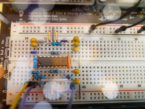
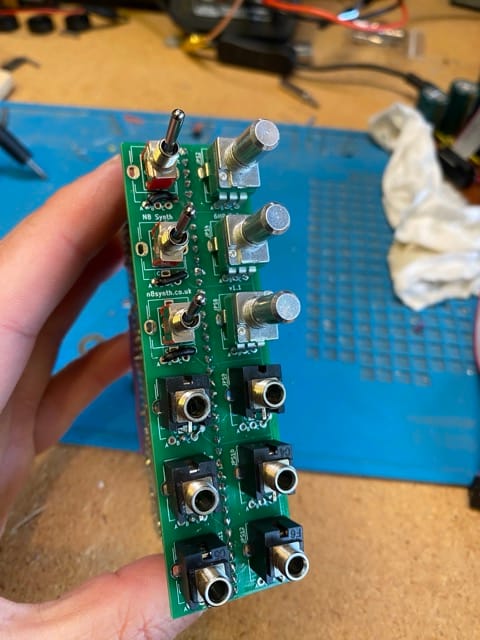
The idea that I could prototype a module on a breadboard or the Labor and transfer the layout directly to a rackable module was so compelling that I immediately placed an order. While I waited for the boards, I started creating a layout for the attenuverter circuit using N8's web-based module designer, and while doing so discovered that these boards have a number of brilliant features:
- You don't have to mess around with power. On the left side of the breadboard (center and right in the photo above) you get alternating +12V/GND pads, and on the right is alternating -12V/GND.
- There are pads for a Eurorack power socket (10 or 16 pin) and filtering caps at the bottom of the board, and the power cable pads are double-sided (!) so you can put the socket on either side of the board.
- The double-sided pin headers on each side of the breadboard give you flexibility on how you interconnect and stack.
- The control boards (left in photo above) each have a bus with pads next to each component that you can use for ground.
These features made it dead simple to lay out the circuit. You can view the layout yourself by downloading the file below and opening it in the module designer.
It took me about eight hours total over two days to solder up the boards. I added the power connector and caps and tested polarity before I soldered any components to the rails. After that, I worked my way from center out, top to bottom. The pads on the board are high quality and took solder very well. Any lousy joints are due to my technique.
The next step was to hook it up to my benchtop Eurorack power supply for testing. I have a Hantek 2D72 digital oscilloscope which works really well for testing modules. I use the scope's signal generator to create an input signal with a known waveform, frequency, and amplitude, patch that into the input, then probe the output with the oscilloscope. During testing, I discovered that my original layout had a wiring error for the feature selector switches – future Paul, remember that pad C stands for "Center" when wiring switches. After fixing that minor issue, everything worked as expected!
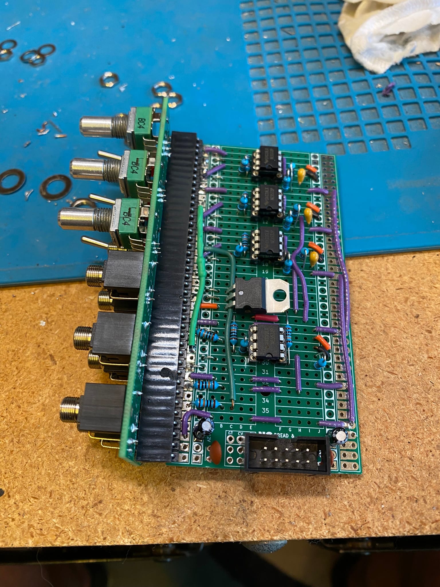
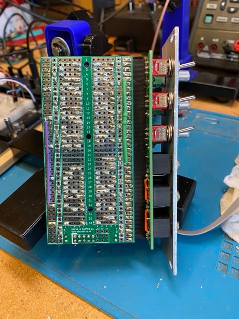
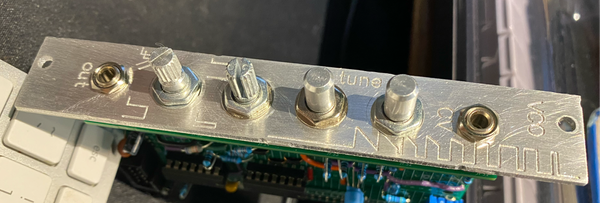
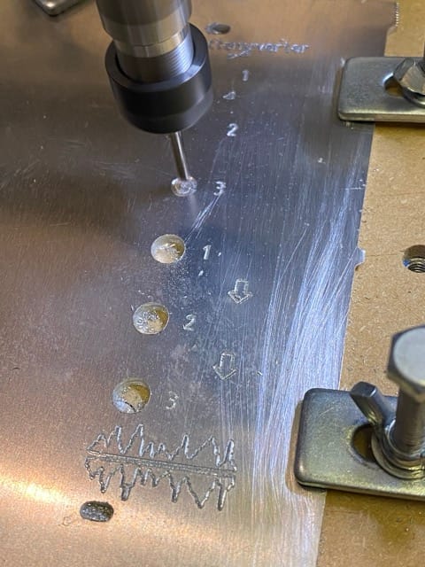
I designed the faceplate in Fusion 360. I do wish that N8 provided an SVG or spec sheet that shows the dimensions of the holes for components that can be mounted on their control boards. I measured the 6 HP board that I used and found that the holes are laid out on a 17mm grid center-to-center. I milled the faceplate out of 2mm aluminum, and after milling, I sanded the front with 220 paper to get a nice matte finish. The controls fit, but it was tight, so I'm thinking that maybe my measurements are not 100% accurate.
The module is racked up next to my LFO now. I'm sure I'll use it in one of my #Jamuary sessions. Listen for that sweet wobble!

