Baby-10 Power Subsystem
Early morning obsessive thoughts about my sequencer project lead me to build a split-rail power supply.


At least three times last week, I've woken up at around 5:30 am thinking about my Baby-10 design. I realized the value of having a gate output per step after reading this exsertus.com blog post: an 1/8" gate out jack on each step plus a reset input eliminates the need for SPDP switches and makes the whole sequencer feel much more modular in that you set the sequence length with a patch cable. I bought some switching 1/8" jacks to replace the SPDP switches and am in the process of reworking the step component wiring – pitch potentiometer, LED, and (now) switching jack – to conform to the patchable design.
I also came to the conclusion in those early morning hours that I want the sequencer to be able to drive my Moog synths at their "native" voltage levels. The Werkstatt VCO accepts input at -5V to +5V and gates at 0 to +5V. The Subharmonicon uses similar VCO voltage levels, though the gate accepts 0 to +10V. At first, I didn't understand negative voltage at all. Positive was positive and ground was negative, right? I did some searching and found David Halliant's "Ground is Not your Negative Rail" blog post, and that helped clarify my thinking about voltage. It's all relative, as Einstein might have said. Once I had a mental handle on negative vs. ground, I decided to add an opamp to the sequencer to scale the output of the 4017 to the Moog voltage range. This meant that I needed an power supply that provided negative 5V, a virtual ground, and +5V to drive the opamp. This is known as a "split rail" power supply, and they are common enough in Eurorack systems that I found plenty of example schematics to use as a base for my sequencer.
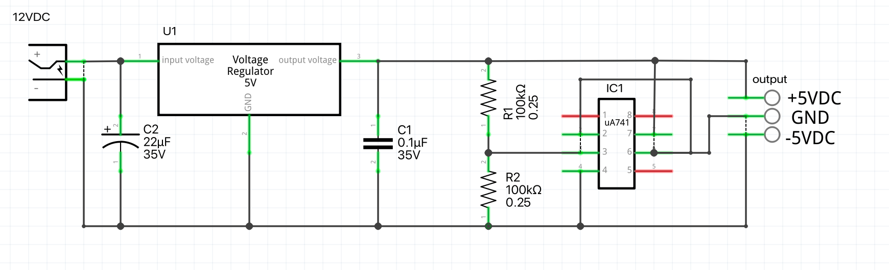
Here's the design for a split rail supply that I put together:
In case you are finding this page through a search engine, I want to make sure you know that I'm not a hardware engineer. This circuit was globbed together from stuff I found on the internet, and I cannot in any way guarantee that it is correct or even works at all.
Note that the voltage regulator is a 7810. I couldn't find a 10V regulator part in Fritzing, which I just started using for this project. The left half of the circuit is a standard DC voltage regulator that provides a steady 10V. On the right, we have a uA741 opamp configured as a voltage splitter per this Circuits Today blog post.
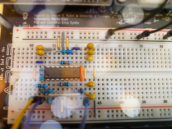
Just to make things interesting, I decided to build this circuit on a stripboard with the intention of hooking it up to the main board with jumpers later. Fritzing has a tab for doing stripboard layouts, and this is what I came up with:
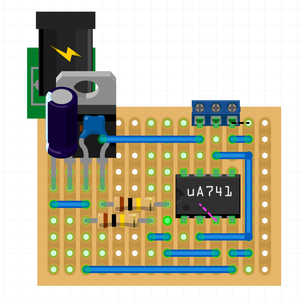
I thought this wasn't too bad for my first attempt using this, or any, layout software. I used my Dremel to cut the indicated traces (the four traces under the 741 are cut) and mounted up the components. I didn't realize that the components go on the non-copper side of the board and you solder them on the copper side, but fortunately figured that out before I made any unsolvable errors. Here's the top side of the completed board:
And the bottom:
Note the jumper of shame at the lower right. Voltages all checked out – my multimeter read -4.96V between pin 6 of the opamp (ground) and the negative rail and +4.96V at the positive rail. Fritzing was great for doing the circuit design and I learned a lot about stripboard layout. Next steps are to hook this up to the breadboard where I'm prototyping the sequencer to double-check that it works and to solder up the pot, jack, and LED for one of the steps to verify my new design for the reset signal. Oh, and also figure out where I'm going to put another jack for reset in. Hmmm...