Building a Baby-10 Sequencer
Paul starts work on a Baby-10 control voltage sequencer.

I've started design work on a Baby-10 control voltage sequencer that I intend to use to drive my Werkstatt and possibly the Subharmonicon. When I say "design", I really mean just picking out which schematic that I want to build, because there are tons of options – do a quick search for "baby 8" or "baby 10" or "modular step sequencer" and you'll see what I mean. To narrow down the search, I listed out some features that I think are important:
- Based on CMOS chips. Sure, I could code up a really nice sequencer on an Arduino or microcontroller, but I've been writing code professionally for 25 years. I want to get practice at building hardware, not software.
- Variable pattern length up to 10 steps.
- Must be able to drive the VCO on the Werkstatt at a minimum. VCA, VCF, and LFO would also be great.
- Option to use built-in or external clock.
- Must have Das Blinkenlights!
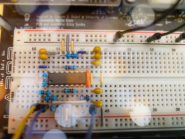
I'm primarily using Eddy Bergman's design which they describe in their blog post, Synthesizer Build part-8: 8 STEP SEQUENCER as a starting point. It's relatively simple – there are only 10 types of discrete components in the circuit – and the post does a great job of discussing tradeoffs and recommended modifications in a way that I cpuld understand. Additional shout-out to -minus- for their stripboard layout post on ElectroMusic, which gave me ideas about how to wire up the pots and LEDs, and the MFOS Ten Step Analog Sequencer article from Music From Outer Space is full of information that I will certainly need to refer to for this builld.
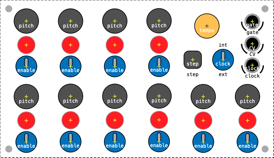
Considering the current space on my music production desk, I chose this small, slope-front enclosure for the project. It isn't obvious in the product photo, but the case has an aluminum panel. I've got a bit of a natural wood esthetic going right now, though, so I'm going to cut a piece of veneer to fit and use that for the first iteration of the control panel. The image at the top of the post is the layout I created using Amadine, a vector drawing program for macOS. For each step, the "pitch" circle is the frequency pot, the red circle is an LED, and the blue "enable" circle is an SPDP switch. When flipped up towards the LED, it will route the step signal to CV out. In the middle position, no signal will be sent, creating a rest in the sequence. The bottom position will route the step signal to RST on the counter chip, starting the sequence over again. I feel like this control layout is going to be very playable.
I'll post build-in-progress pictures as it comes together.
Update, May 21st, 2021:
I was looking around for ideas on how to do the point-to-point wiring of the front panel recently and found a blog post from exsertus.com that I hadn't seen before. Like the MFOS design, this module has a gate output jack for each step. I had thought those jacks weren't really that interesting because I couldn't envision a case where I would gate different synths from the same sequence. BUT! The exsertus design has a jack for resetting the sequence, and I suddenly realized that, instead of using switches to set the sequence length, I could patch a gate jack to the reset jack. Such modular, so flexible! So now I'm considering replacing the switches with switching jacks for gate signals...