Clock divider

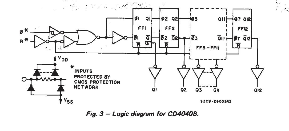
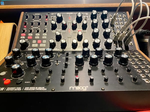
When I was practicing with my Eurorack and Moogs for my September performance at the Electronic Music Open Mic, I realized that I didn't have any modules that would let me subdivide the quarter note pulse from the Subharmonicon. All of the instruments felt like they were in lockstep, marching at the same beat in a static rhythm. Naturally, my thoughts turned to clock dividers. I'd experimented with the CD4040 binary counters on a breadboard and had a few laying around, so I decided to build a module based on that chip.
I found a great blog post on CMOS Clock Dividers on the MidCentury Modular web site which helped me avoid several issues:
- The CD4040 triggers on the falling edge of the input clock signal, not the leading edge as you might expect. Inverting the clock signal with a NOT gate turns the rising edge to a falling edge.
- The outputs also need to be inverted, again with transistor NOT gates. I also added a current-limiting resistor to the output as well.
In my first version of this module, I added a SPDT switch that ran either +5V or GND to the NC pin on the reset jack. My thinking was that I could pause the clock divider by flipping to +5V. It technically worked; flipping the switch sent a high signal to the reset pin on the 4040, but because the outputs are all running through NOT gates, the effect was that every output went high at once. Not very musical. I changed the design to run the input clock signal through the switch before it hits the NOT gate on the main board. Turning off the clock input ends up "freezing" the outputs, which is good enough.
Here's my version of the MidCentury Modular design:
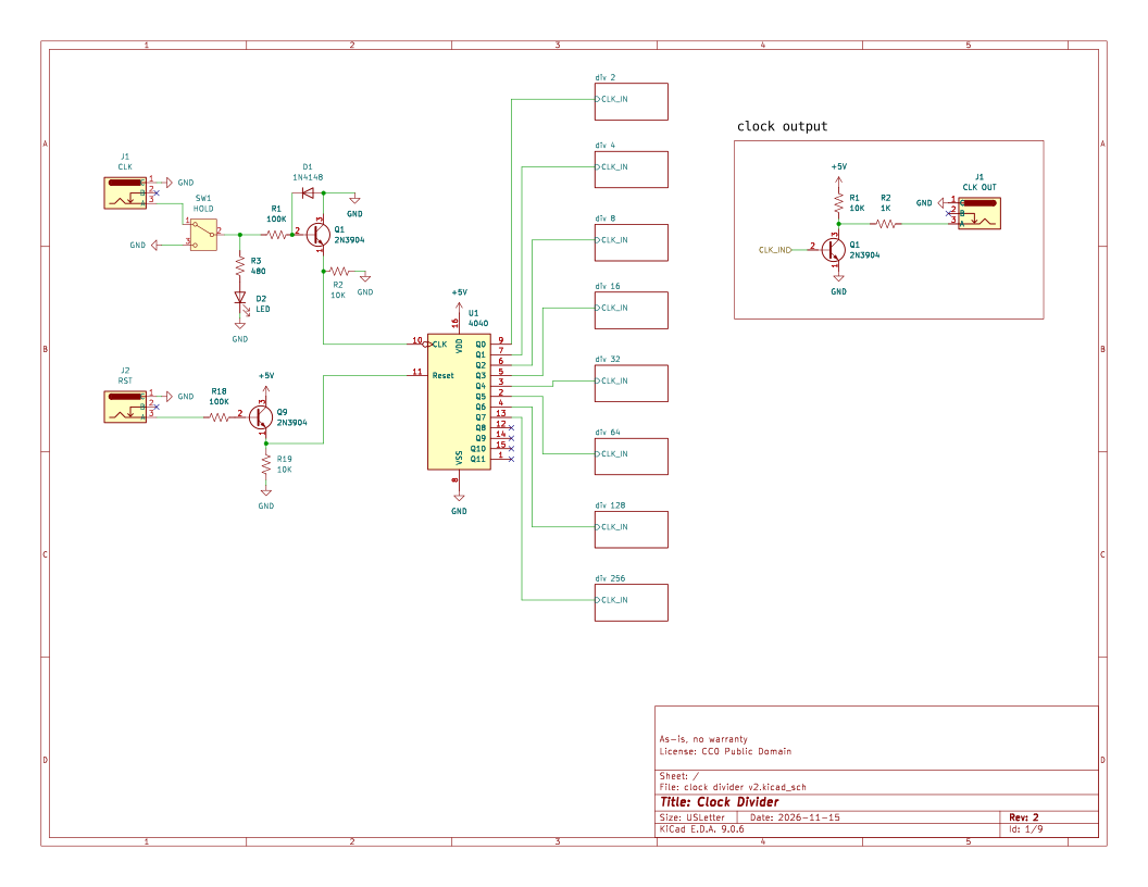
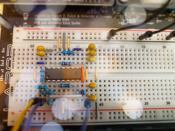
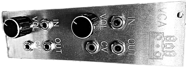
Pretty simple in the end. I built the module using N8Synth boards.
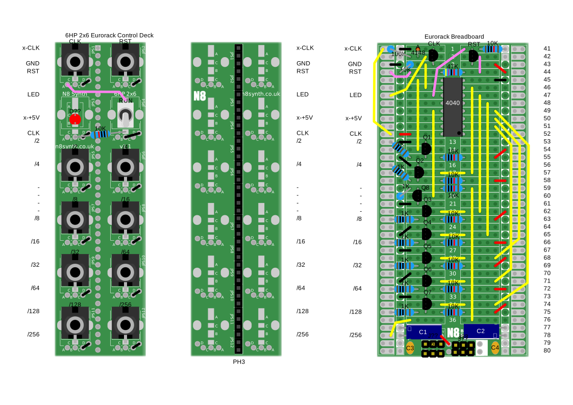
Note that the whole circuit runs on 5V, and the N8 boards are set up for +/-12V rails on either side. You can see that I pulled the 12V pins from the 16-pin connector and jumped the 5V pad to the +12V pad (the red wire near C1). Not shown is a jumper on the back of the board which connects the bottom left power pad, row 40, to the right power pad. That bodge gave me +5V on both sides of the breadboard.
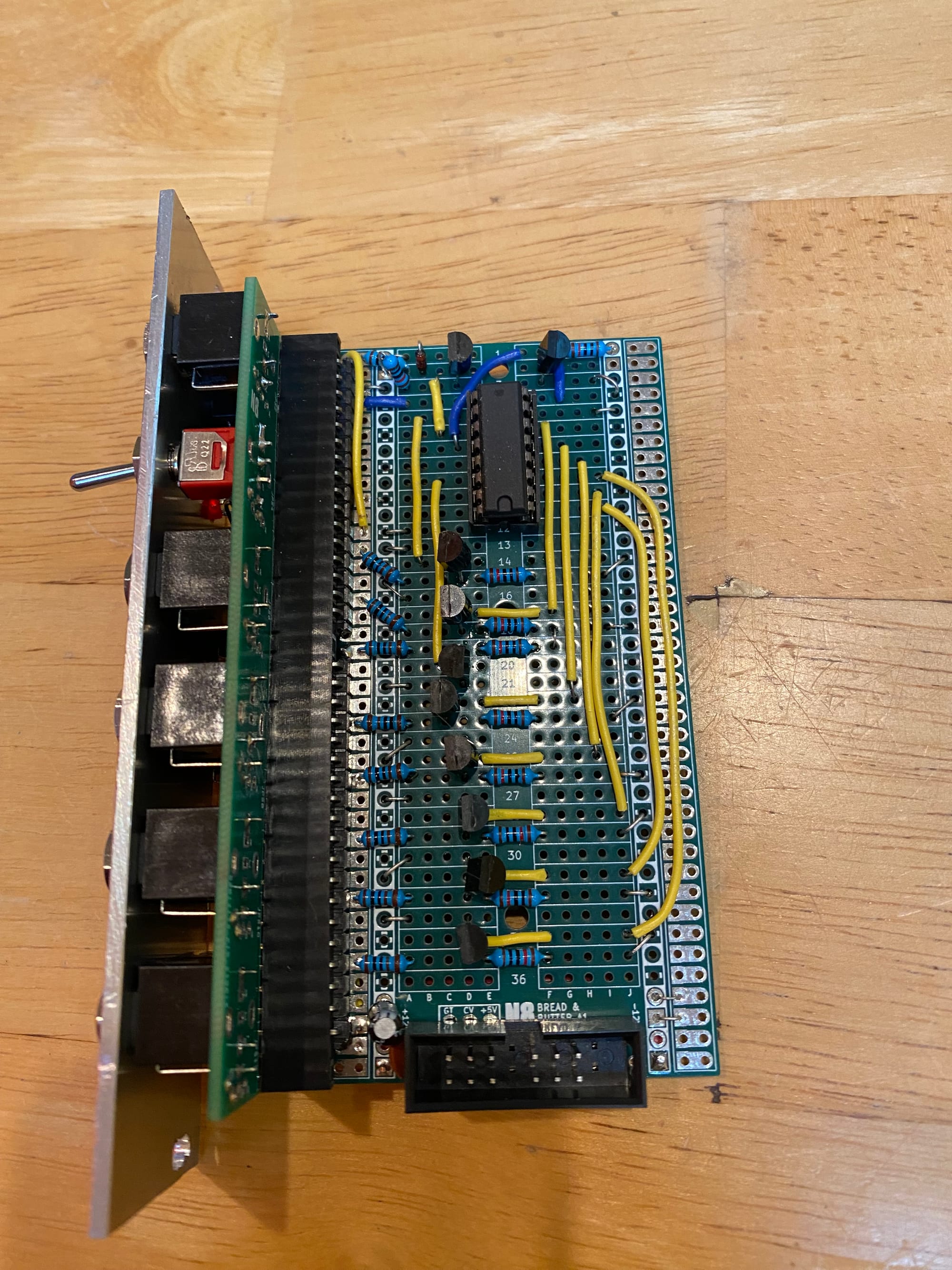
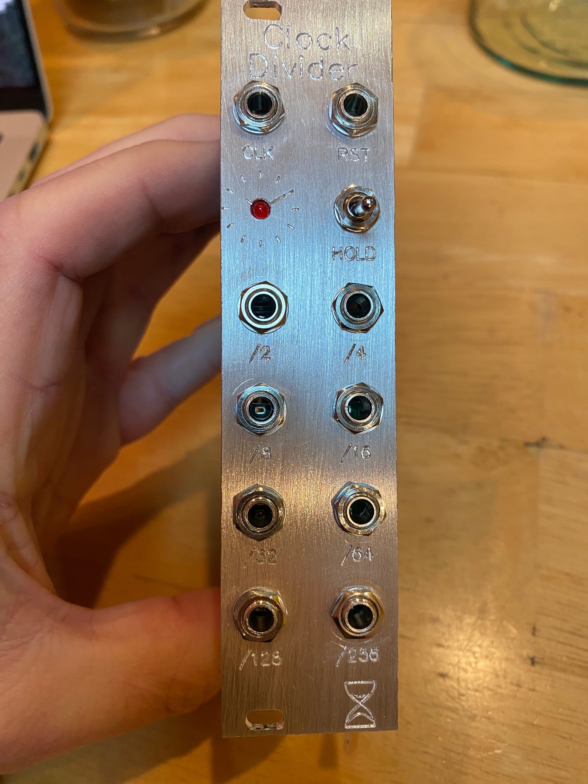
I racked it up and plugged the sync out from my new Korg SQ-1 ($30 at Habitat for Humanity reStore, can you believe it?) into the CLK input and the /2 output into the CLK input of the Subharmonicon. I know, someday my carefree attitude towards connecting DIY equipment to expensive Moogs is going to bite me on the ass. But it worked! The Subharmonicon ran at half the rate as the SQ-1. This is going to open up lots of triggering possibilities, and I'm excited to put together a patch that uses this new module to build more interesting rhythms.