DIY Cha Cha VCLFO Module
In June of 2023, I got a great deal on a Rackbrute 6U and 3U set of cases from a coworker. I mounted my Subharmonicon and DFAM in the 6U for a nice, compact synth unit. The semimodulars don't take up the whole width of the case, though, so I started thinking about what modules I wanted to add to the two Moogs. Modulation sources were at the top of my list. I found several open source repos with hardware designs for LFOs and settled on the Vox Machina Cha Cha voltage controlled LFO as my starting point.
At the beginning of this project, I had the idea that I would mill the circuit boards using my Genmitsu 3020-PRO MAX. One of the reasons I purchased the mill was to make one-off boards for experimental projects. I actually had some success with converting the Gerber files into Gcode and running the programs on the mill:
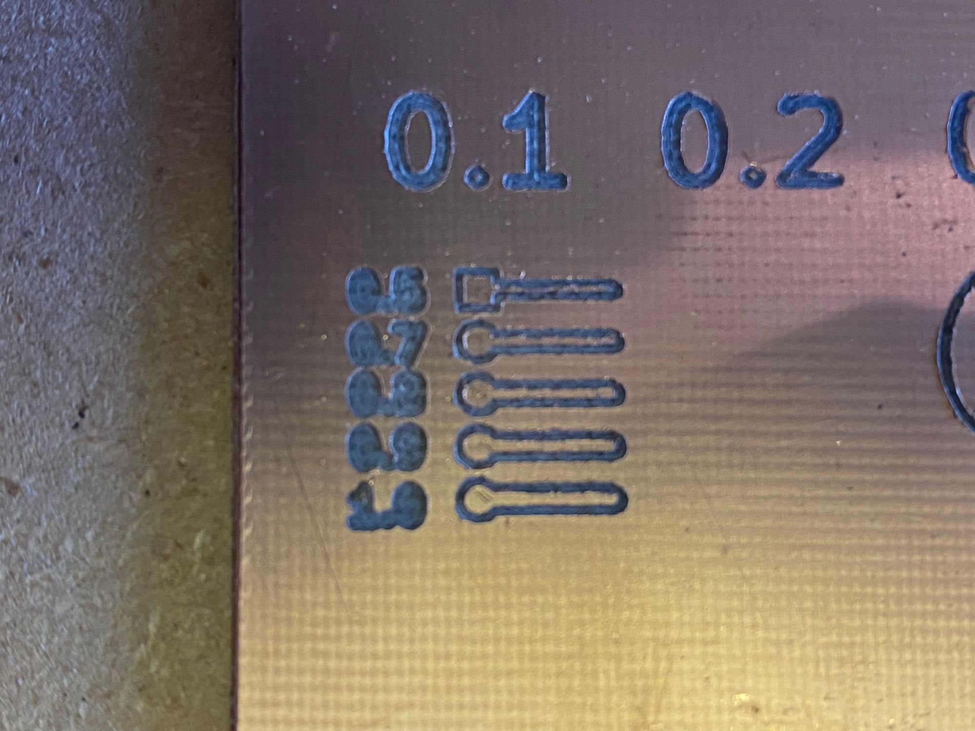
In the end, though, the traces on the existing board design were too narrow and close together to mill accurately.
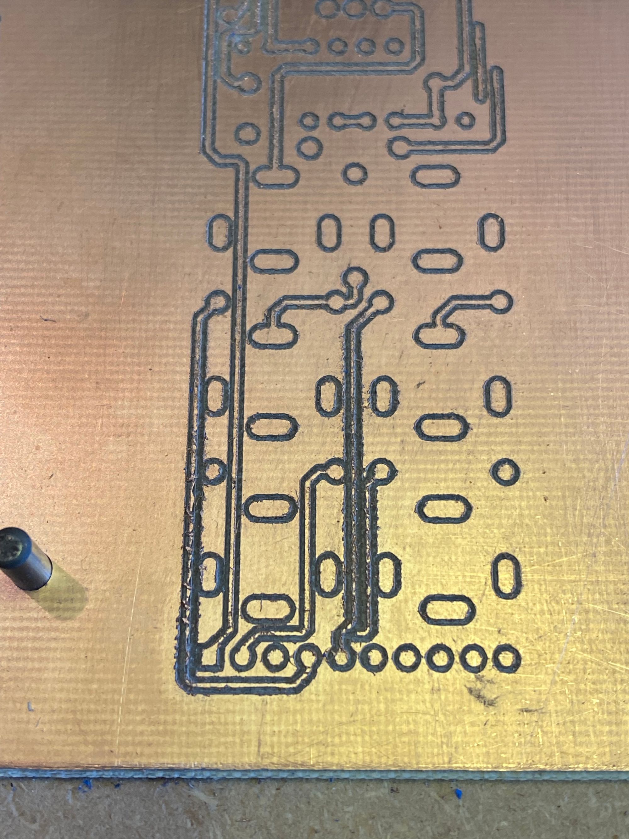
I experimented with changing the trace width in EasyEDA without much success. At that point, I decided that I wanted the LFO more than I wanted to be able to mill a circuit board, so I started working on a stripboard layout for the two module boards. This was surprisingly difficult! I went through four iterations in November and December 2023. During the end of year holidays, I finalized the layouts and assembled the boards.
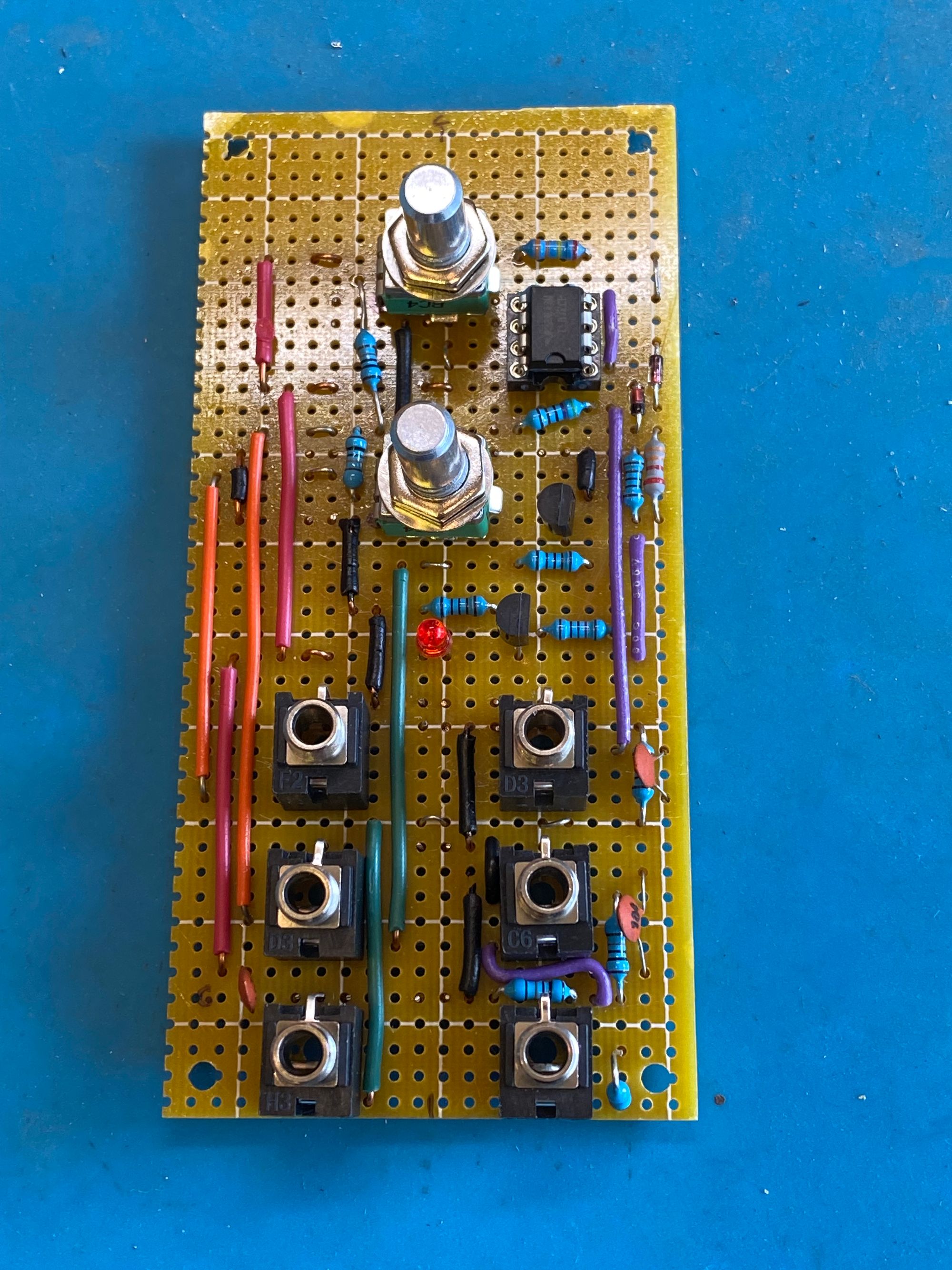
Early testing of the control board looked promising. I ran a triangle wave into the LED circuit, which lit up as expected. During construction, I discovered and fixed a layout issue with one of the jacks. On to the main board!
I started by assembling and testing the power socket and conditioning circuit (top of the main board), then added a TON of jumpers on the back side of the board. In retrospect, it might have been easier to use actual stripboard, where the traces run the full width of the board, than to use Veroboard, which has the five pad traces. Soldering all of those jumpers took a long time.
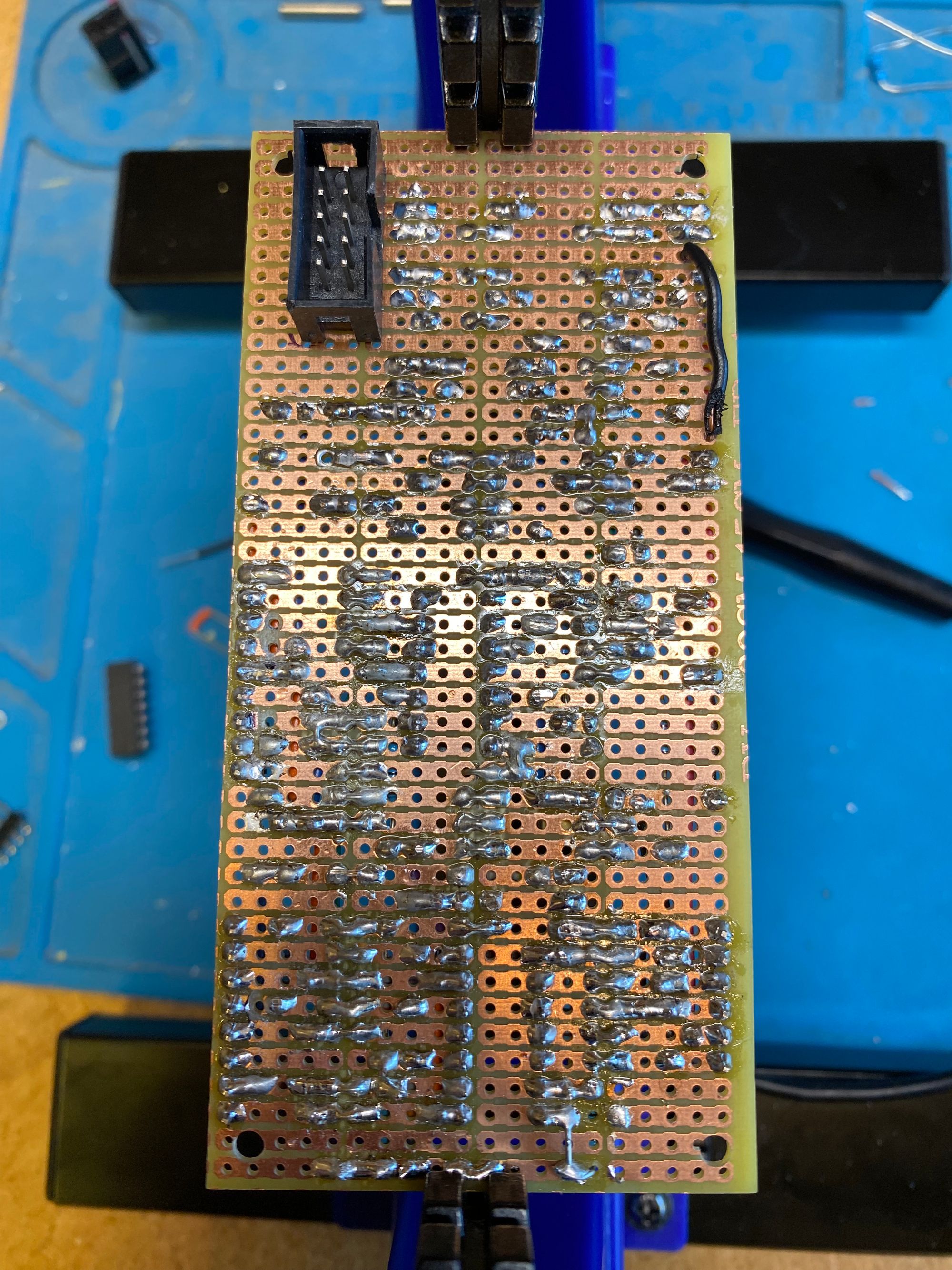
I assembled the rest of the components working from center outward, top to bottom. I found another layout problem about halfway down: I had an extra row! I ended up using that for ground, which worked out great.
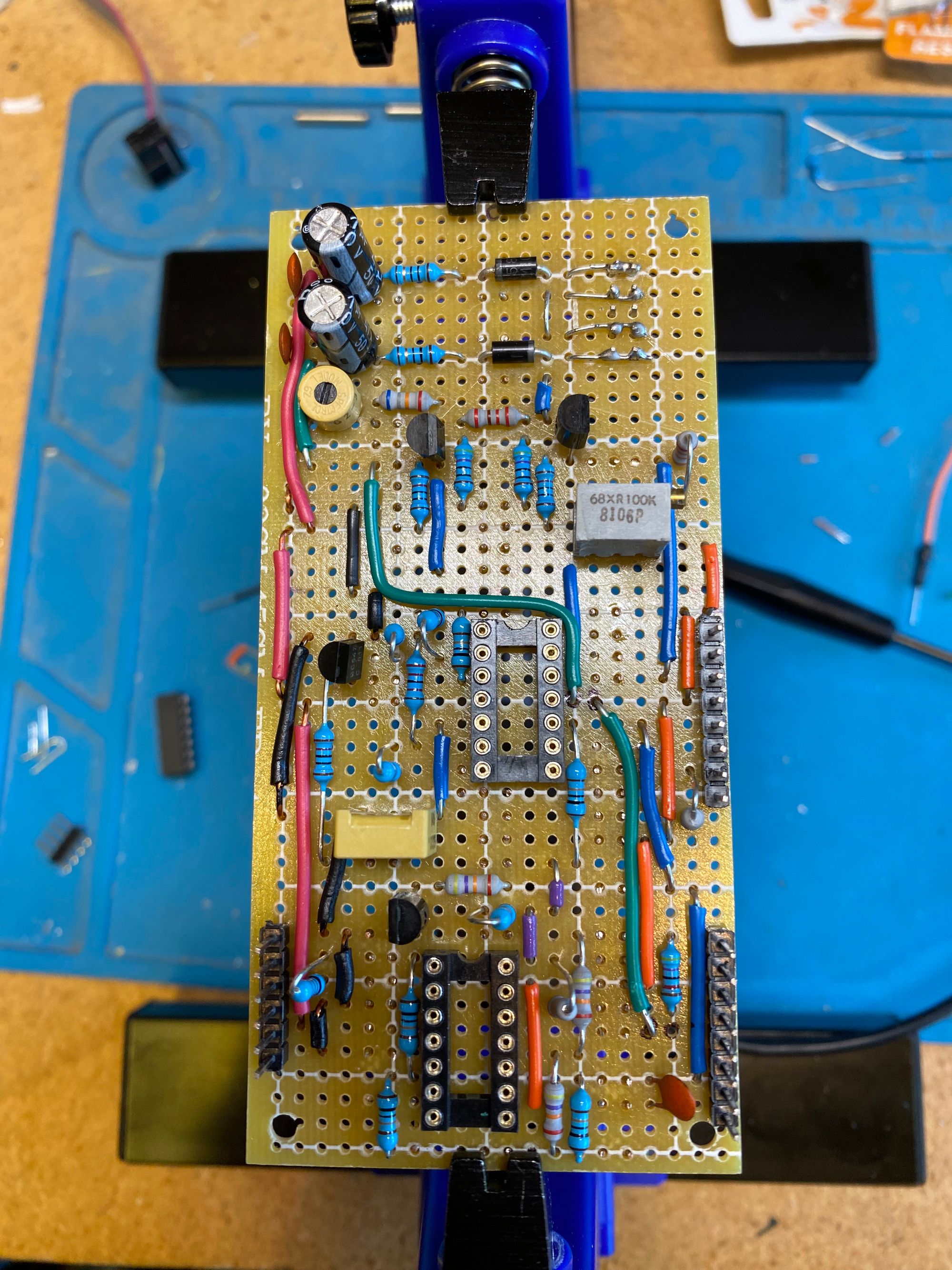
Once the board was assembled, I socketed IC1 (lower socket) and probed the triangle and saw outputs with my scope. Success!
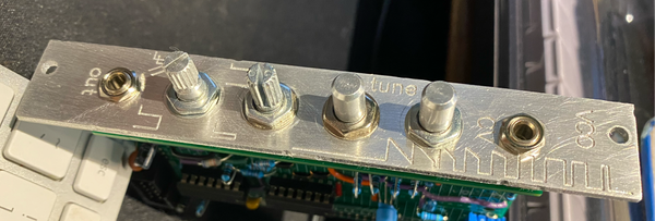
I also designed and milled the faceplate from 2mm aluminum.
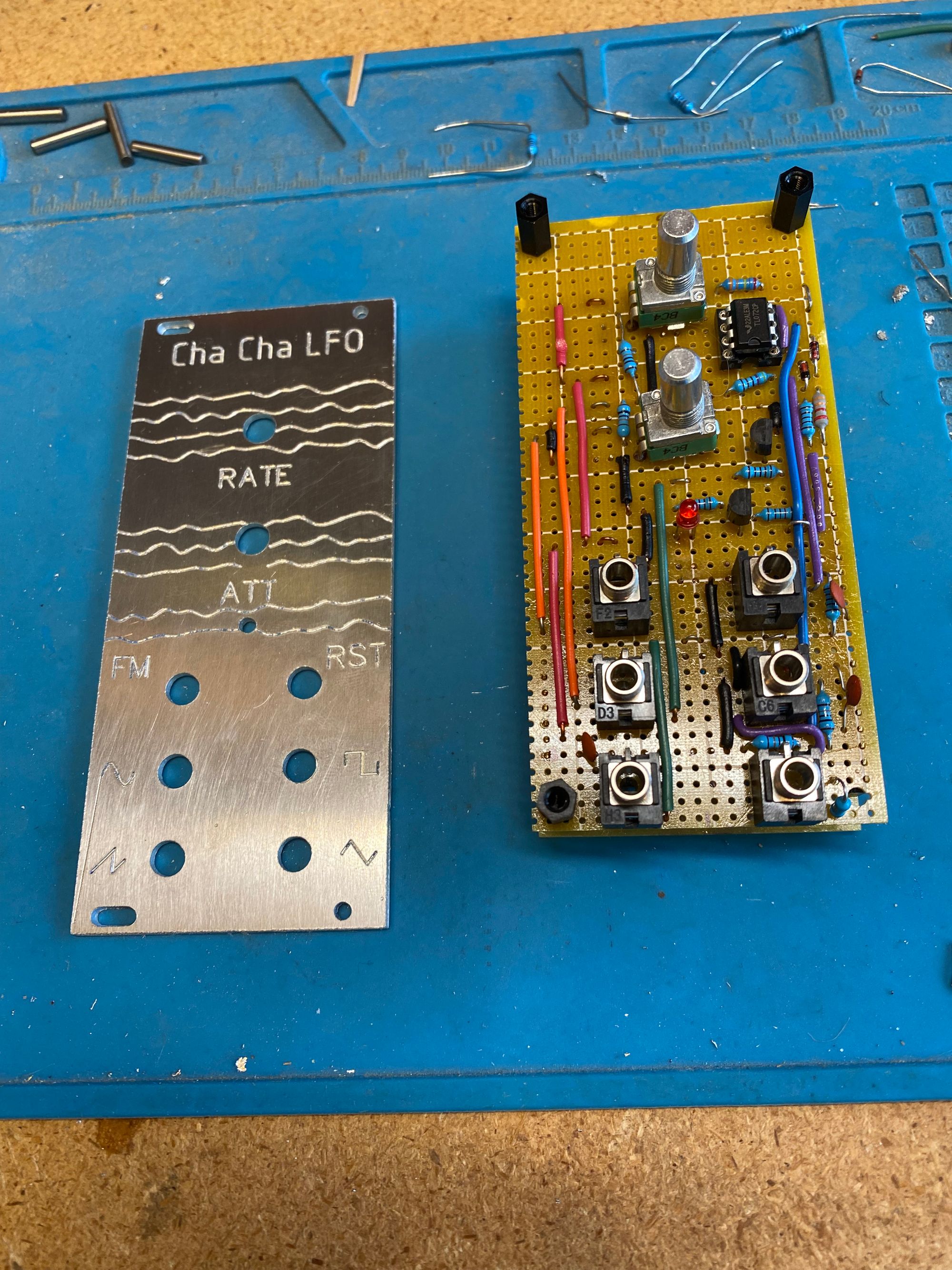
(update, Jan 2025 !!)
The LFO module has been working great, except for the reset input. I had to disconnect it from the opamp as it was constantly resetting the oscillator. I haven't had the motivation to de-rack and debug, frankly...

