Moritz Klein VCA build
Despite a few setbacks, my home-built modular system now has voltage-controlled dynamics.

In my VCO post, I naively wrote, "Now I just need a dual VCA..." Famous last words! I decided to build two of Moritz Klein's VCA circuits in a 6HP module. The MKI VCA consists of two transistors, an opamp, a couple potentiometers, and a bunch of resistors. Relatively simple, right?
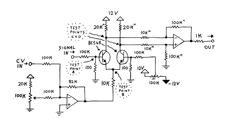
Let me tell you, there is more going on than meets the eye. Moritz devotes 26 pages of the kit manual explaining how each subunit functions and how they all work together to create voltage controlled amplitude. But this is a build post, so I'm going to skip the theory and talk about my frustrations, rework, and ultimate success with this circuit. Read the manual and watch his build video series for a deep dive.
I continue to be a big fan of the N8Synths DIY module platform. I recently stocked up on Bread & Butter breadboards and Control Boards in anticipation of US-UK trade going down the tubes. As usual, I started the project by laying out the circuit in the Module Designer.
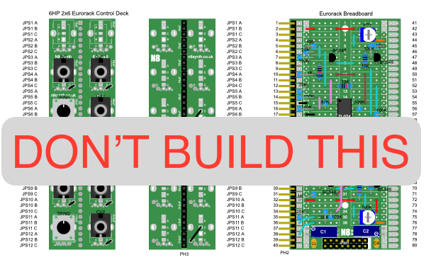
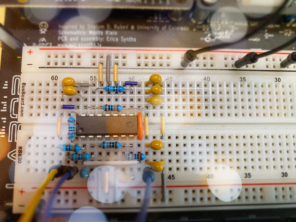
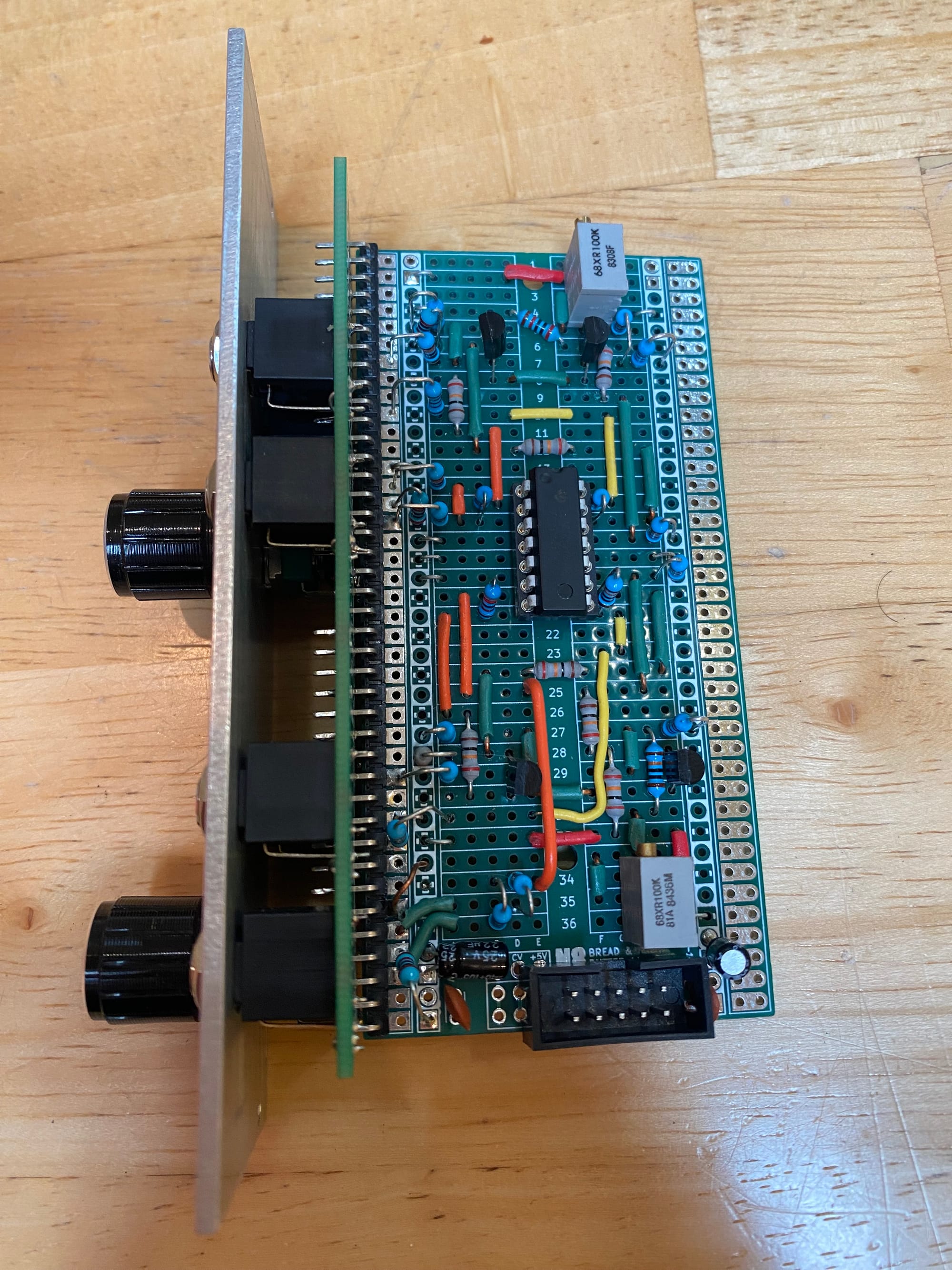
I assembled the main board in two evenings, which is pretty fast for me. I had decided to solder the main board directly to the control board to minimize the depth of the module. Before I attached the control board (permanently), I wanted to do at least some minimal testing to ensure that the circuits were operating correctly. I hit on the Frankenstein solution of using three test leads to connect pads 13 through 15 to a 100k potentiometer mounted on my Labor and another lead from Labor's signal generator to connect to pad 7 to provide an input waveform. I fired up Labor, hooked up the scope to test points B and C, and saw mirror-image triangle waves at test points B and C as described in the manual. However, there was no signal at pad 16, JPS6A. I discovered that I'd soldered the 100k feedback resistor on the output opamp module between pin 14 and oblivion instead of pins 13 and 14. I moved that guy over one hop and the combined, amplified waveform appeared at the output. The second VCA circuit gave me similar grief, but after more testing and checking, I was able to get that one working as well. Here's the final layout on the breadboard:

If you are so inclined, you can use this layout file for the N8 Synth Module Designer as a starting point for your own VCA:
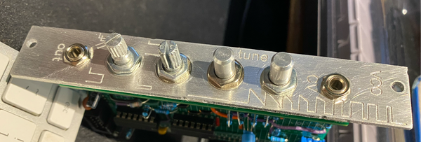
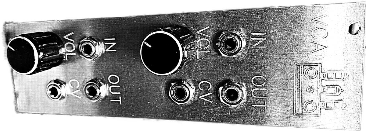
Here's how the module board turned out:
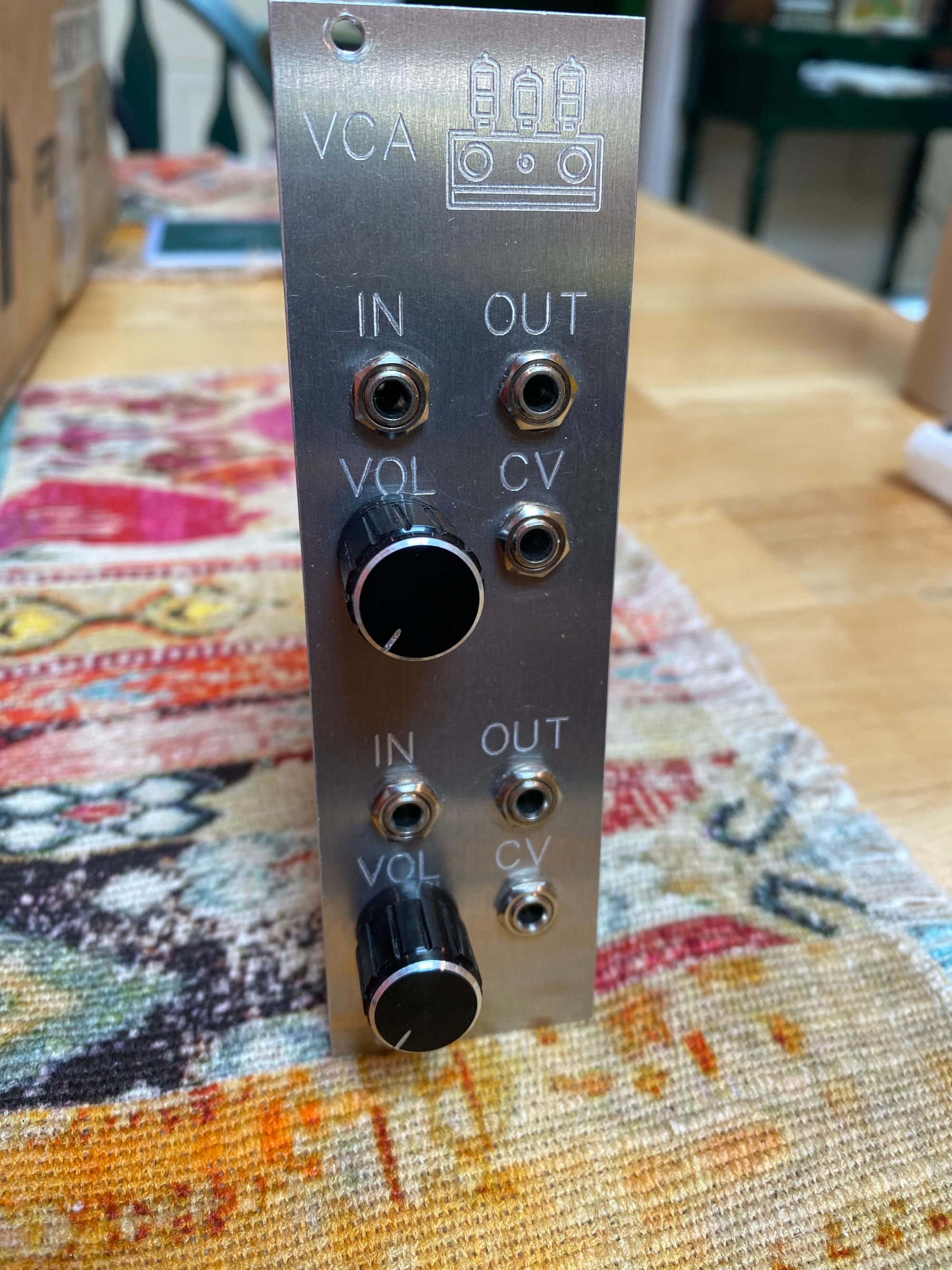
As usual, I designed the faceplate in Fusion 360 and milled it on my Genmitsu 3040-PRO. For this module, I used 2mm 6061 aluminum plate instead of the 5052 aluminum I had used for previous modules. I felt like 6061 worked much, much better than 5052 – it machined cleaner, with fewer burrs and cleaner cuts. I later discovered that 6061 is a better choice for machining, so I'm going to stick with that for future modules. I've read that 6061 is also good for anodizing and will report back on the results when I do my next batch.
I racked the module and patched in my VCOs to the two inputs. For CV control, I used my Arturia Keystep, plugging the CV output to the VCO CV input and the GATE output to both of the VCA inputs. The result was actual, discrete notes coming from my modular! I noticed a snap/click at the start of the notes, but I'm not too worried about that because I don't plan on using the GATE signal as my CV control for the VCA in the long term.
The biggest learning from this build is that I can use the Labor prototyping board to help troubleshoot and test as I go along, saving a lot of time and frustration. With two oscillators, I think the dual VCA will be all I need for the time being. Of course, now I need a better CV source for the VCA.