Baby-10 Clock Assembly

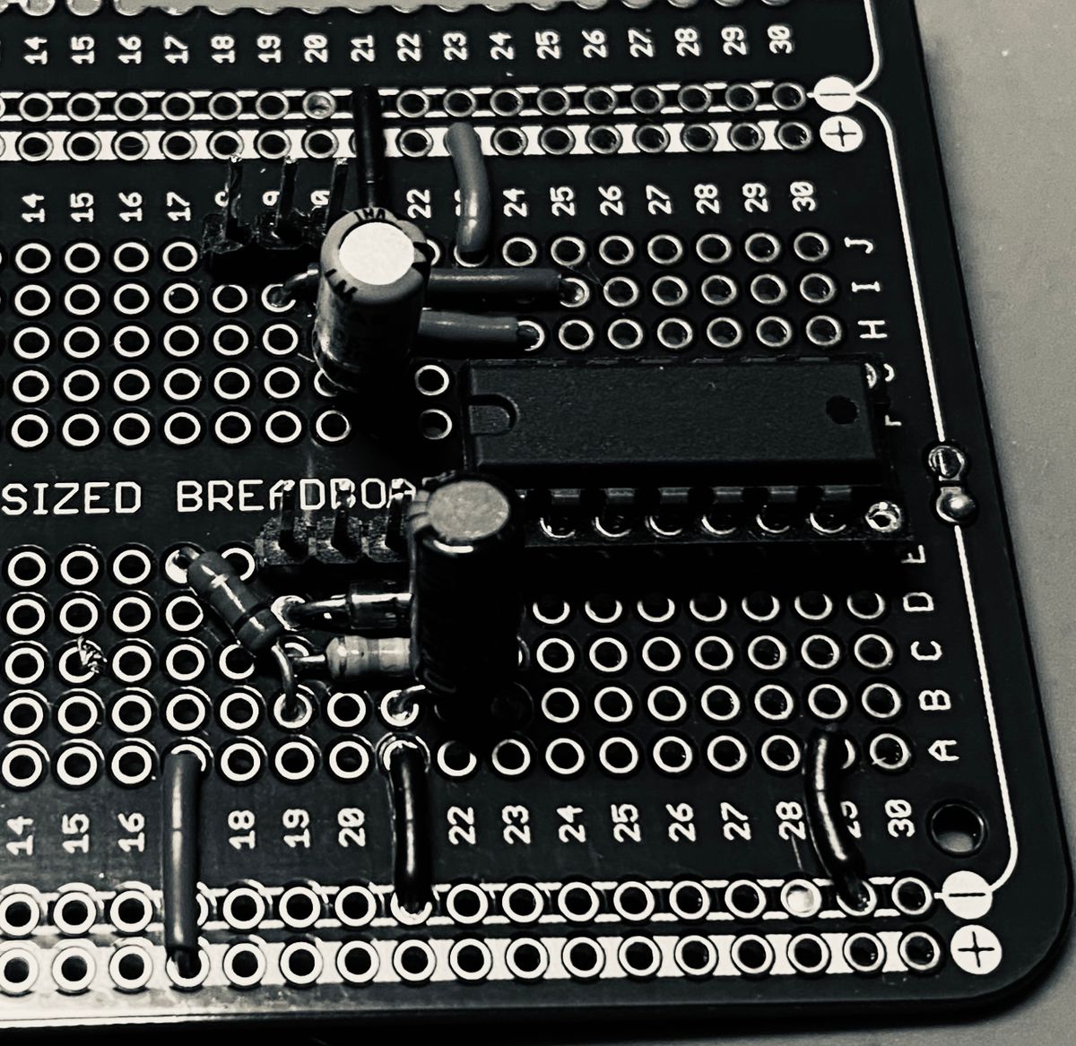
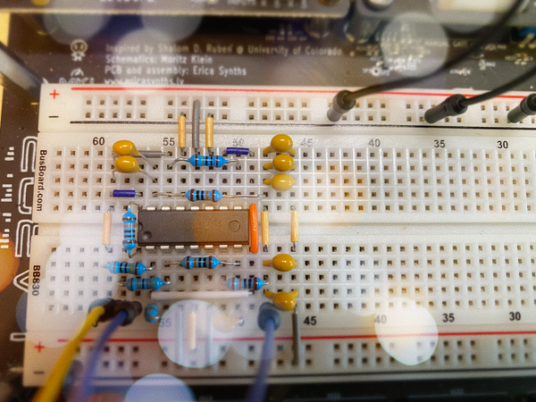
Time to commit and solder up this board. I decided to start with the circuits around the CD40106 decade counter chip:
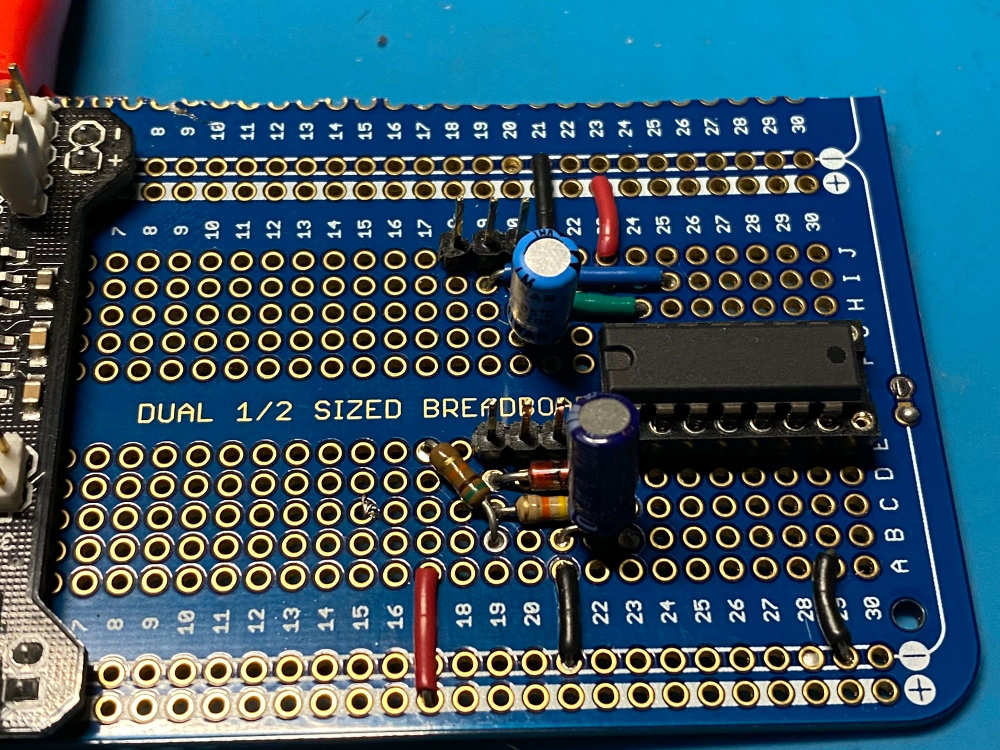
The 40107 decade counter chip is mounted in a socket on the right side of the board. The circuit on the bottom half of the board is a switch debouncer. The three pin header plugs into a momentary switch on the front panel, and the debounced output is available at pin 2 of the IC. The circuit on the top of the board is the internal clock. The header on rows 18-20 leads to the wiper and leg of a 100k potentiometer on the front panel. The output pins will run into a basic OR gate, then over to the CLK input of the 4017.
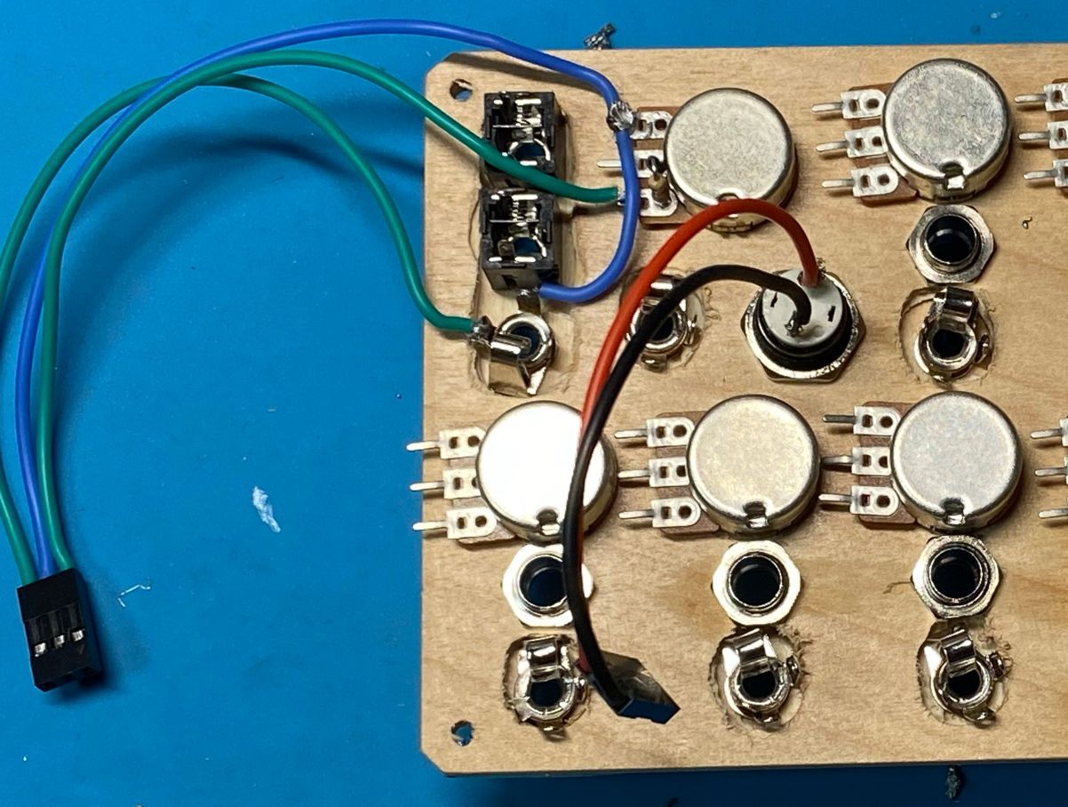
The switching jack underneath the two non-switching jacks (the black boxes at the upper left) is set up to accept an external clock signal. The blue wire in the photo above is the output of the internal clock circuit. When there is no plug in the jack, the internal switch is closed, and that clock signal flows to the green wire on the left of the jack. When a plug is inserted, the switch is opened, and the green wire gets the signal from the tip of the jack and the internal clock is disconnected.
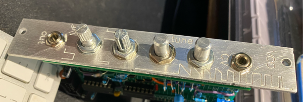
EDIT (28 June 2021): The front panel wiring shown in the photo above didn't work. When I looked at the signal coming from the 1/8" plug on the oscilloscope, I saw a flat line. I unplugged the front panel and ran the two green leads to a different potentiometer, and saw a nice square wave. Being a practical sort, I simply cut the blue lead out of that cable and am getting the clock signal from the green wire that comes from the jack.
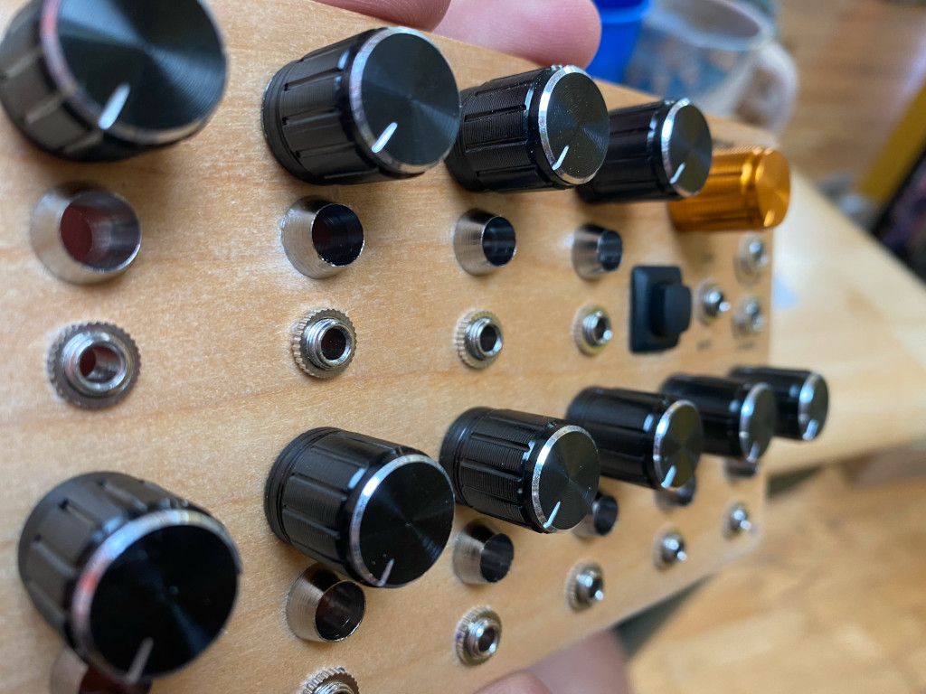
Here's the obligatory glamour shot of the front panel...
Next up will be soldering the 4017 decade counter to the board and connecting it up with the clock. After that, it's the step I'm dreading a little bit: connecting up the ten sets of pots, LEDs, and switching jacks, plus a ground. The back of the panel is about to turn into a mess of wires. There are a few other tasks, like grounding all of the unused inputs on the 40106, and I still have to decide whether to add an opamp to scale the CV voltage from 0 - 10V down to -5 - +5 V.