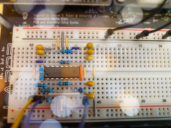
Baby-10 step subassemblies
Wiring up ten sets of components -- one for each step of the sequencer -- is tedious, but also a good learning experience.

"It's one of the most fun panels for the synthesizer but one of the most tedious to build."
-Eddie Bergman
If you're following along with this series of posts, you know that my build is heavily based on Eddie Bergman's 8 STEP SEQUENCER project. I can't say that Eddie didn't warn me about the tediousness of wiring up the front panel. I tried to think up a clean way to put together the components for each sequencer step, and considered ideas like putting each step on its own mini-stripboard. In the end, I couldn't figure out how to make it work physically. With a shrug and a mental reminder that this is supposed to be practice and fun, I started soldering up each set of step components point-to-point. For the first four steps, I mounted the components in the front panel and soldered in place. It was hard to get the soldering iron tip in those tight spaces, though. I eventually realized that I should be assembling each pot/LED/jack step separately and then mounting the completed subassembly to the front panel. Here's how I did it:
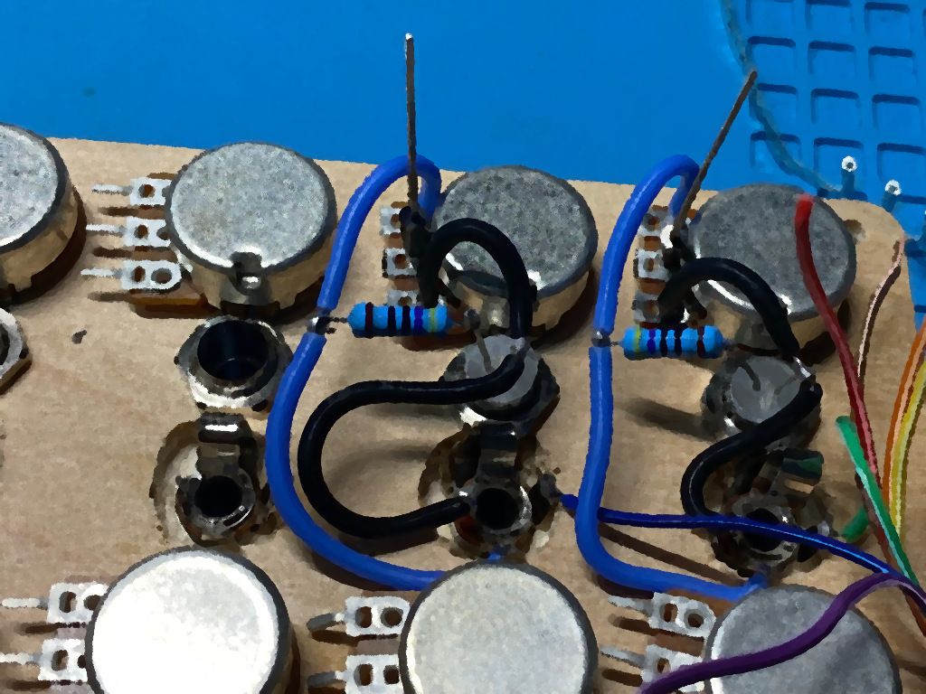
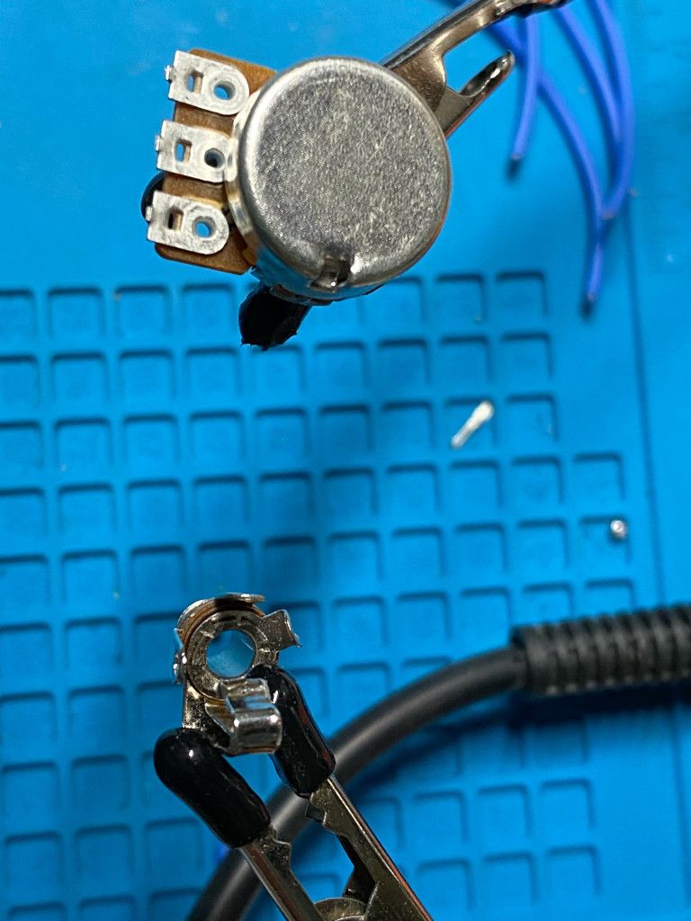
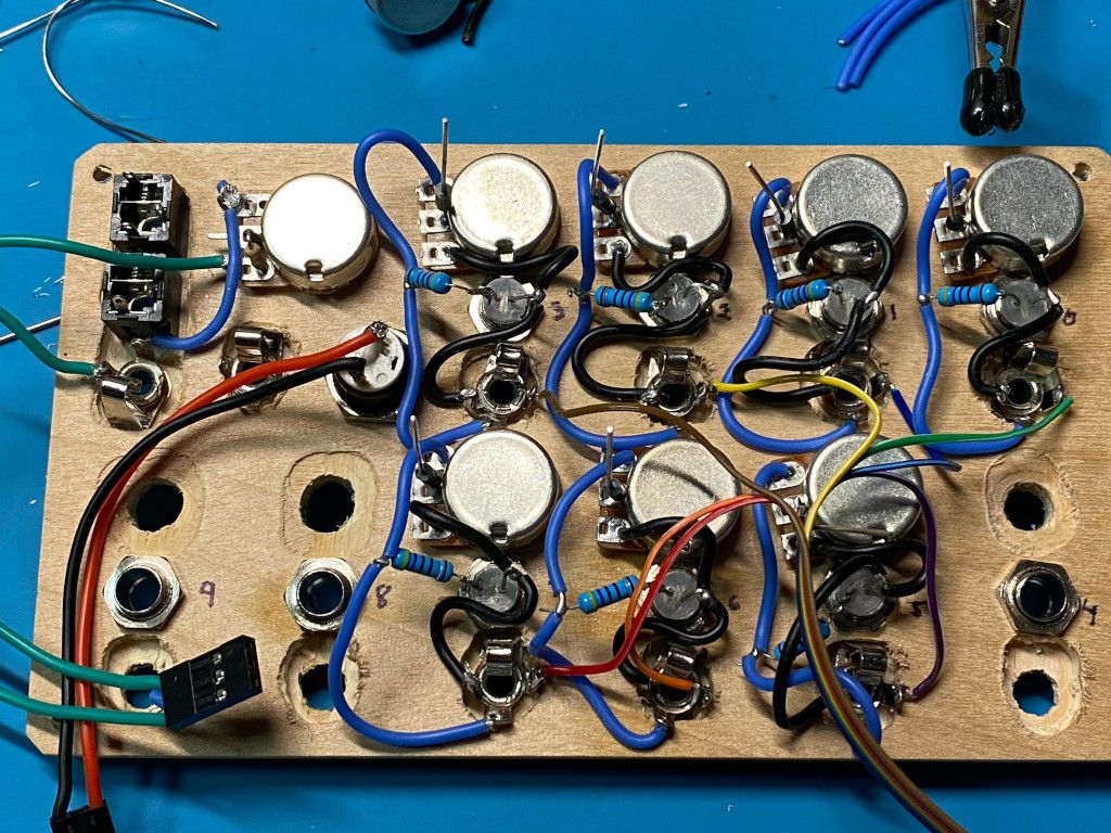
Each step consists of a 100k potentiometer, Schottky diode, LED, resistor, and a switching 1/8" jack. The diode is connected to the wiper of the pot and provides the 0-10V CV output signal. One side of the pot is connected to the jack and the other to ground. The LED and resistor are connected in parallel to the jack. The "switching" side of the jack is connected to one of the output pins on the 4017B decade counter.
I started by using the clips on my soldering station to hold the pot and socket in place:
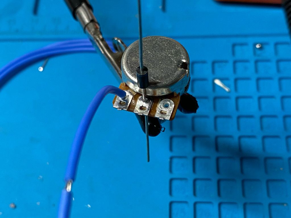
Next, I soldered the diode and output wire to the pot:
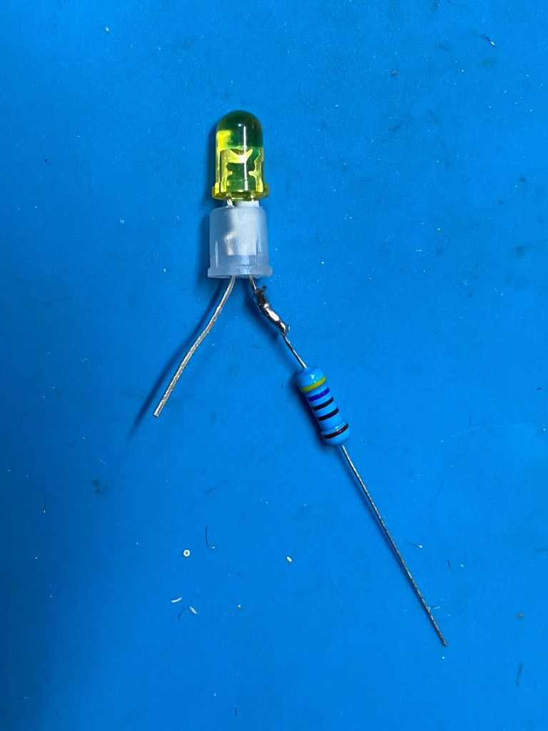
Separately, I put the mounting gizmo on the LED and soldered the resistor to the positive leg. There's a little piece of heat shrink tubing on the positive leg inside the gizmo to help prevent shorts:
I then wired up the pot to the LED/resistor, and then to the socket.
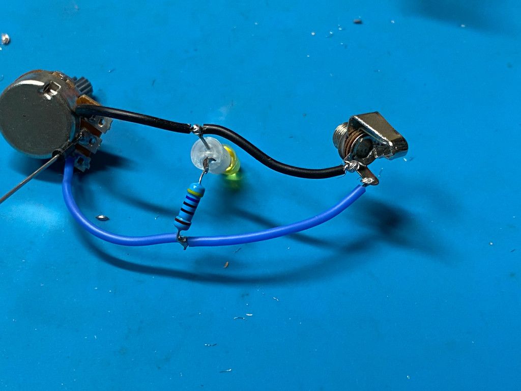
Once a subassembly was finished, I inserted it into front panel and screwed on the mounting nuts on the front. I had previously created a ribbon cable to carry the output pin signals from the 4017, so the last step in the process was to solder the correct ribbon cable wire to the switching jack. Voila!
The first time I plugged it in, I saw that the header part of the ribbon cable wasn't making good connections with the main board. You can't really fix those fiddling little crimp connectors, so I cut the whole thing off and made a new one. So far, the new connector seems to be working fine.
As you can see from the picture, just four more steps (and another ribbon connector) to go. Even though it's a long way from being functional, I'm learning a lot and getting my soldering practice in so I'm having fun.