Dual Power Supply Project

I recently finished my Baby-10 sequencer and used it to drive my Werkstatt as part of a recent musical project. While there were a couple of problems with the build that I'm not completely happy with, completing this project has really sparked my interest in building synthesizer modules from scratch. I feel like it would be a lot of fun to find schematics that look interesting, add CV control points, and connect them to other devices. My experience with the Baby-10 and Atari Punk builds showed me that it would help a lot to have a test platform for these types of projects. The OMSynth kit looked like a cool way to play with circuits, but it unfortunately is no longer available. I decided to make something similar for my workbench, and the logical place to start was to put together a power supply.
Most of the projects that I've looked at use op-amps, so I knew that I needed a dual output power supply (why?). I didn't really want to mess with 110 VAC and transformers. I also wanted something I could build on a stripboard. I found the MFOS Wall Wart Power Supply schematic and the Syntherjack modular synth wall wart PSU plans, both of which would meet my need for a dual +12V/-12V supply. I considered this adjustable supply from PCBWay as well.
(edit July 10, 2022) Moritz Klein has a video on YouTube called DIY SYNTH PSU which dives into the theory of this PSU design. I highly recommend watching it before starting on this project.
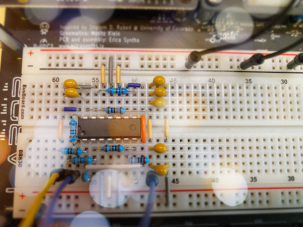
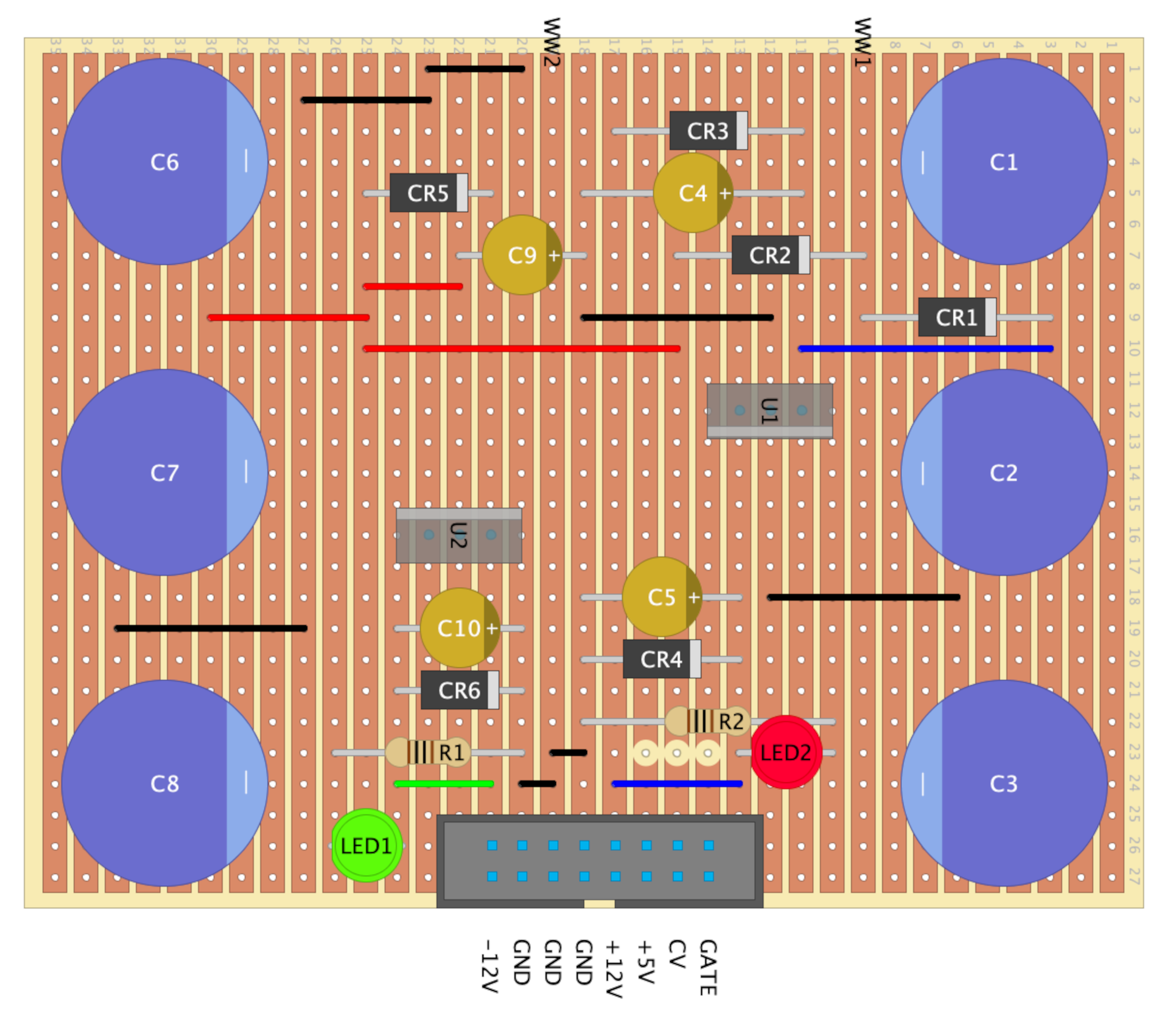
I built the MFOS circuit on a breadboard to make sure I understood how it works. This was the point where I learned that you can’t substitute 1N4146 diodes for 1N4004s (pop!). I settled on a circuit that is mostly the MFOS design with the addition of a box header wired for Eurorack power and indicator LEDs for both the +12V and -12V rails as in the Syntherjack project. I found DIY Layout Creator to be easy to use for the stripboard layout, and the net analysis feature of that program was very helpful when I was validating my board design with the original schematic. Here's the layout and DIYLC project file:
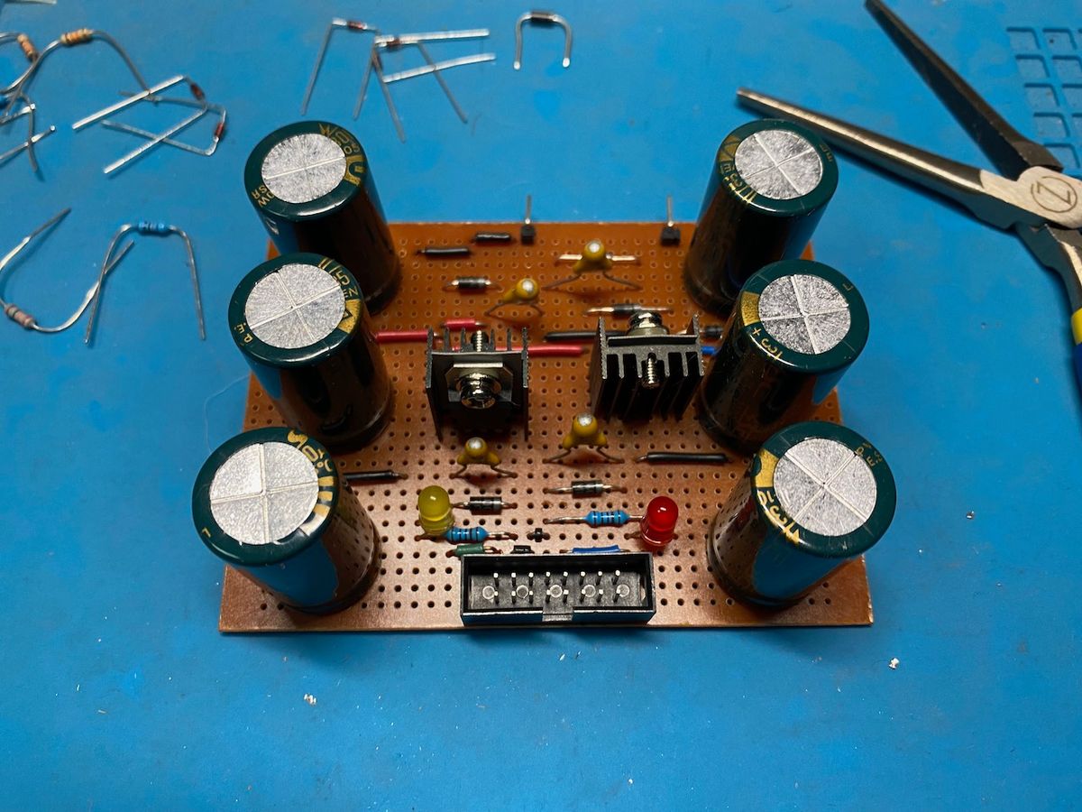
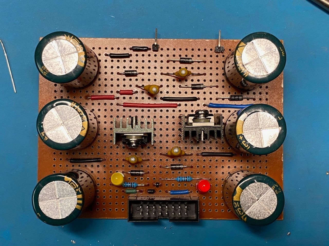
I soldered it all up, crossed my fingers, and plugged it in. The board worked as expected: +12.15V and -12.43V on the positive and negative pins of the header. I’m not anywhere near an expert at using my scope, but the output looks pretty quiet to me. Would I connect it to my Beads, if I had a Beads? Probably not. Like I said, I’m a beginner.
When I posted this build on Reddit, user MattInSoCal had some suggestions about the tantalum capacitors:
Move the four 1uF capacitors C4, C5, C9, C10 as physically close to the regulator ICs as possible. This helps keep the regulators from going into high-frequency oscillation. Ray mentioned they need to be there but not their actual purpose. I recommend changing them to 10-100nF ceramic capacitors (you can use film if you like; it doesn’t matter). Decades of experience in the electronics industry prove this as valid.
One thing to mention if you are working with capacitors on the larger side, like the ones in this project: remember that they can hold a fair bit of charge. It’s one thing to know this intellectually, and another to see the indicator LEDs stay lit for a full minute after you unplug your circuit. Be careful out there!
| Qty. | Description | Value | Designators |
|---|---|---|---|
| 1 | LM7812 +12V Voltage Regulator | LM7812 | U1 |
| 1 | LM7912 -12V Voltage Regulator | LM7912 | U2 |
| 2 | Resistor 1/4 Watt 5% | 1K | R1, R2 |
| 2 | LED | LED1, LED2 | |
| 6 | 1N4004 General Purpose Rectifier | 1N4004 | CR1, CR2, CR3, CR6, CR4, CR5 |
| 6 | Capacitor Electrolytic | 3300uF | C1, C2, C3, C6, C7, C8 |
| 4 | Tantalum Electro (35V) | 1uF | C4, C5, C9, C10 |
| 1 | 9 to 12 VAC Output Wall Wart | 12VAC Output | |
| 1 | 16-pin box header connector | 2x8 |